


Processing and Handling Technologies for Cover Glass Used in Satellite Solar Cells and Their Application to Mass Production
Optimizing the Handling of Thin Glass, Preventing Cracks and Chipping, and Establishing Mass-Production Design Guidelines for Strengthening and Coating
Cover glass used in satellite solar cells is not merely a protective component. It plays an extremely important role in protecting cells from radiation, ultraviolet light, and micrometeoroids and orbital debris (MMOD) while maintaining long-term optical transmittance.
At the same time, as satellites need to perform better and weigh less, cover glass is becoming increasingly thinner. While this contributes to weight reduction, it also creates trade-offs, including reduced mechanical strength and greater handling difficulty.
One issue that frequently arises in manufacturing environments is when a process works at the prototype stage but breaks down in mass production. This is often caused by the emergence of process variations, a high dependence on handling conditions, and the prevalence of work that relies heavily on skilled operators.
This article summarizes practical design and process guidelines based on these challenges, with a focus on application to mass production.
Explore EG-S1: Ultra-Thin Cover Glass Designed for Space Applications

EG-S1 is designed to balance high optical transmittance, mechanical strength, and environmental resistance required for space use.
View EG-S1 Details →
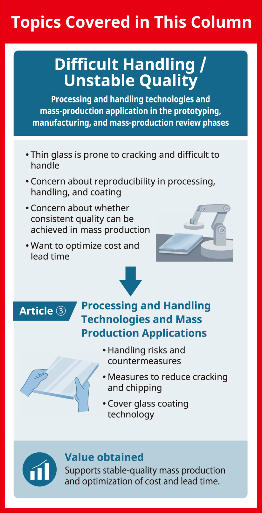
- Mechanical Properties of Thin Glass
- Crack and Chipping Mechanisms
- Risk Points During Handling
- Common Defect Cases in Manufacturing Sites
- Recommended Handling Conditions
- Impact of Cutting and Polishing Processes
- Suppressing Edge-Originated Defects
- Specific Measures for Reducing Chipping
- Types of Coatings for Space Applications
- AR Coatings
- Conductive Films for Antistatic Purposes
- Reflective and Shielding Films, Such as Ag Mirrors
- Causes of Coating Defects
- Key Points for Ensuring Reproducibility

01/Understanding the Properties and Failure Mechanisms of Thin Glass
Mechanical Properties of Thin Glass
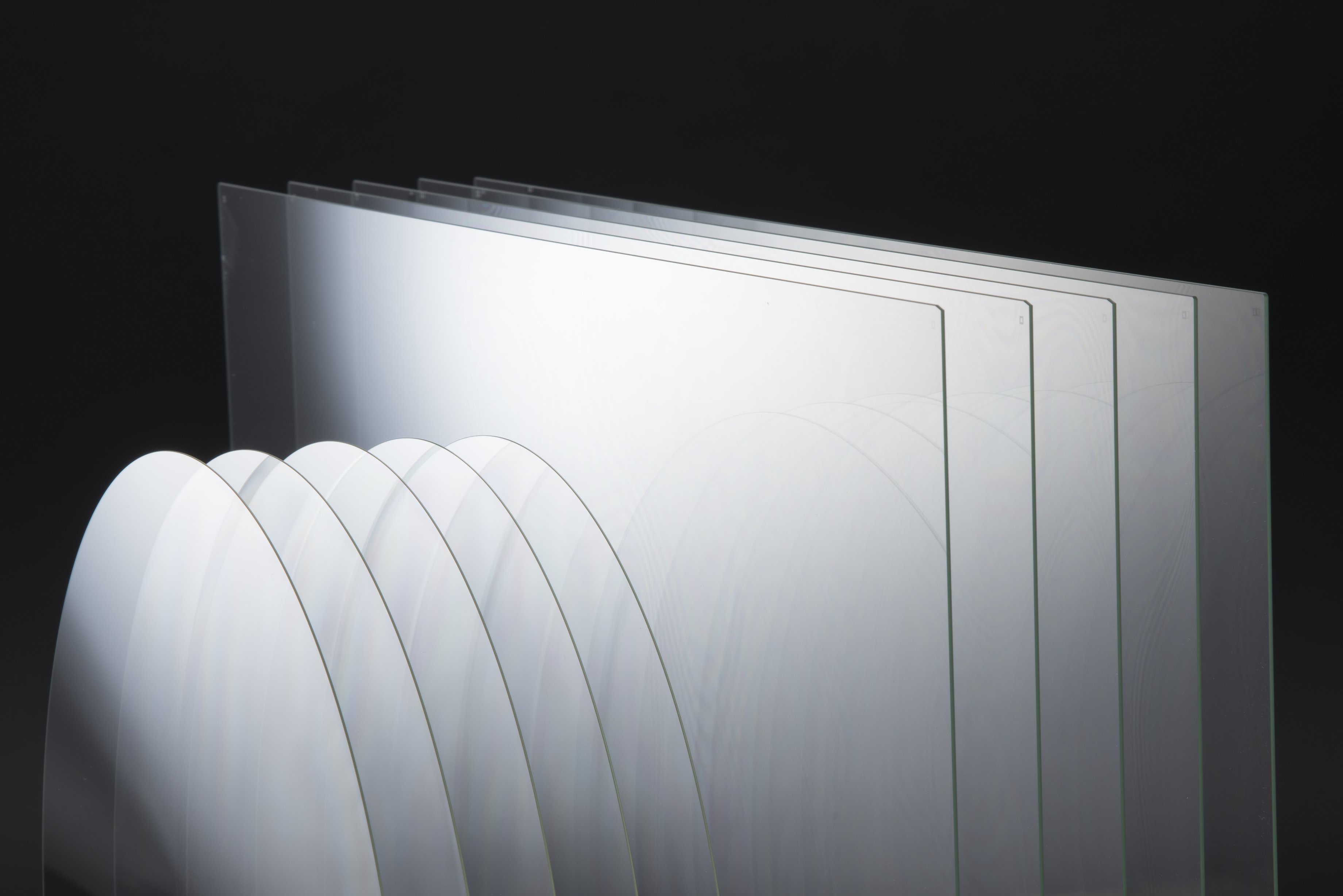 The strength of thin glass does not decrease in proportion to its thickness. In practice, its strength is governed primarily by sensitivity to defect size. Glass strength is controlled by surface and edge defects rather than by the material’s bulk. As the glass becomes thinner, the relative impact of these defects increases. In addition, reduced flexural rigidity leads to greater deformation under external force.
In particular, when defects such as foreign particles or bubbles are present, microcracks formed around them can cause stress concentrations, resulting in a significant reduction in tensile strength. For this reason, it is important not only to reduce the number of defects but also to control the shape of cracks around them so that stress concentrations are less likely to occur.
In EG-S1, a cover glass for space applications developed by AGC, technologies for controlling the shape around defects are incorporated into the manufacturing process in order to suppress stress concentration originating from such defects. This is because, in space applications, what matters is not only the material’s strength but also whether stable strength can be maintained even when microscopic defects are present.
It is widely known that static fatigue fracture in glass substrates is mainly caused by stress corrosion due to moisture (H₂O). In space, however, the effect of humidity is relatively minor compared with that in terrestrial environments. Even so, moisture originating from encapsulants and humidity control during the manufacturing process remain important, and environmental control is required in mass production.
Furthermore, while thinner glass is less affected by process-related scratches caused by its own weight, edge strength becomes relatively more dominant. Because edge strength is strongly influenced by edge quality, the edge-finishing method is extremely important.
In EG-S1, high-precision edge processing is performed across multiple process steps to ensure the high level of reliability required for space applications. Especially in thin glass, edge quality is directly linked to final yield and long-term reliability. Therefore, a design approach that considers not only the material itself but also the quality of processing is essential.
In other words, the essence lies not in the strength of the material itself, but in how well defects and edge quality can be controlled.
Crack and Chipping Mechanisms
The main origins of fracture can be categorized into edge-originated fracture, the growth of microscopic defects (also known as subcritical cracks), and contact stress or localized stress concentration.
In thin glass in particular, edge quality strongly influences the fracture mode. If edge quality is insufficient, even slight stress during planar bending or transport may lead to fracture. Since different fracture modes can occur in different process steps, improving first-pass yield becomes difficult.
By contrast, glass that has undergone high-quality edge processing tends to exhibit more limited fracture modes. In EG-S1, controlling edge quality to a high standard has confirmed that the primary fracture mode is caused by Hertzian cracks resulting from impact. This means that edge quality has been optimized to the point where localized impact contact, rather than ordinary bending stress, becomes the main risk.
For this reason, it is important to design manufacturing processes to prevent the edges from coming into contact with or colliding with other components. In transport and packaging processes, in particular, it is common to press glass against a physical stopper to position it. However, with thin glass, this can become a new source of fracture.
To reduce these risks, EG-S1 is managed through an integrated quality control approach that covers packaging material design, dedicated pallets, and unpacking methods. In space applications, quality design must cover not only material properties but also how the product is handled during transportation and unpacking.
Edge strength is typically evaluated using a four-point bending test, or 4PB method, in which load is applied in the normal direction of the edge. However, evaluating thin glass used in space applications is difficult. AGC has also proposed a proprietary method to independently evaluate the edge strength of such thin glass.
The key point is that a fracture does not occur suddenly; it is already progressing before it becomes visible. In mass production, the accumulation of this invisible damage leads to reduced yield.
02/Glass Handling: Design Guidelines for Handling Processes
Risk Points During Handling
Thin glass presents different risks at each process step. During the pickup process, localized stress from vacuum suction can become a problem. During transport, thin glass is affected by vibration and deflection. In cleaning and drying processes, stress can also be generated by liquid flow and temperature differences.
In particular, for thin cover glass used in space applications, process-related scratches caused by the glass’s own weight become relatively less significant as the thickness decreases. At the same time, edge quality becomes more likely to dominate overall strength. As a result, even minor contact that would not normally be problematic in standard glass processes can lead to edge-originated fracture in thin glass.
In glass that has undergone high-quality edge processing, the fracture mode also tends to shift from ordinary bending fracture to Hertzian cracking caused by localized impact. For this reason, process design must focus not only on avoiding large loads but also on preventing the edges from contacting or colliding with other components.
Common Defect Cases in Manufacturing Sites
Problems that frequently occur in mass production include cases where suction pads are not soft enough and create point contact, and cases where multipoint support fails to distribute the load uniformly, resulting in localized stress. In addition, contamination by foreign particles can create microscopic protrusions that become origins of cracks.
The positioning method used in transport and packaging processes also requires careful attention. In general, positioning is often performed by pressing the component against a physical stopper. However, with thin glass, this contact itself may cause edge damage.
If edge quality is insufficient, even slight vibration or minor contact during transport can easily lead to breakage. As a result, different fracture modes may occur in different process steps, making it difficult to identify the root cause of defects and improve first-pass yield.
These problems are often caused not so much by flaws in the design itself as by overlooked conditions on the manufacturing floor.
Recommended Handling Conditions
As countermeasures, it is important to design for low contact stress by using surface contact and flexible materials. Maintaining a clean environment, including particle size, and implementing electrostatic countermeasures to prevent foreign particle adhesion are also essential.
For thin glass, it is also desirable to design transport processes so that components do not directly contact the stoppers and to minimize the frequency of contact throughout the process to reduce edge impact. In the packaging process as well, dedicated pallets and cushioning structures designed with microvibration and contact during transport in mind are effective.
In EG-S1, integrated quality control is applied to the glass material; packaging material, including dedicated pallets; and even to unpacking methods. In space applications, it is important to ensure quality not only within the manufacturing process but also during transportation, storage, and unpacking.
If these measures are not thoroughly implemented, breakage in downstream processes and reduced yield may occur, potentially resulting in significant cost burdens.
Explore EG-S1: Ultra-Thin Cover Glass Designed for Space Applications
EG-S1 is designed to balance high optical transmittance, mechanical strength, and environmental resistance required for space use.
View EG-S1 Details →03/Crack and Chipping Countermeasures: Technologies for Reducing Processing Defects
Impact of Cutting and Polishing Processes
The choice of processing method has a major impact on edge quality and defect characteristics. Common cutting methods include scribing, laser cutting, and CNC machining. In general, however, the higher the throughput of a process, the more difficult it is to consistently maintain high edge quality.
Laser cutting is a non-contact process, but microcracks and recast layers caused by thermal effects can become issues. In contrast, with mechanical cutting, microcracks caused by processing stress tend to be dominant. The grit size used in polishing is also directly linked to defect depth and therefore has a significant impact on strength in subsequent processes.
What is important is that, regardless of the processing method selected, if even a partially weak edge region remains, that area can become the origin of a fracture. In other words, the key is not ensuring above-average quality but avoiding the creation of the weakest point.
Especially for large-area glass used in space applications, maintaining uniform quality around the entire edge perimeter has a decisive impact on yield and reliability.
Suppressing Edge-Originated Defects
The edge is the area where a fracture is most likely to occur. For this reason, edge rounding is essential, and keeping defect depth shallow contributes to improved strength.
In thin glass in particular, edge strength often becomes more dominant than surface strength, and edge quality determines the final fracture mode. Therefore, rather than trying to achieve the required quality in a single process step, it is important to combine multiple process steps and reduce defects progressively.
In EG-S1, a design approach is used to stably maintain high edge quality through multiple stages of edge processing. In space applications, even a localized defect can lead to complete fracture. Therefore, process design must focus not on achieving average quality but on avoiding localized weak points.
Specific Measures for Reducing Chipping
To reduce chipping, it is important to optimize cutting speed and processing stress conditions. During processing, protective film should also be used to protect the surface, and the process should be designed in stages, moving from rough processing to precision processing.
In addition to processing conditions, it is important to avoid edge impacts during post-processing transport and storage. In thin glass, particularly with high-quality edges, even minor contact can cause Hertzian cracks from localized impact, potentially leading to breakage in downstream processes.
The key point here is not to reduce defects to zero but to manage them in a state where they are less likely to grow and to design processes that avoid creating localized weak areas.
04/Cover Glass Coating Technologies: Ensuring Film Deposition Quality and Reproducibility
Types of Coatings for Space Applications
 In space applications, cover glass may use antireflection (AR) coatings, conductive films for antistatic purposes, and reflective or shielding films, such as silver (Ag) mirrors and cut filters. These coatings are used individually and often designed as multilayer structures that combine multiple functions. As a result, optical, mechanical, and thermal properties must be achieved simultaneously.
AR Coatings
AR coatings are intended to reduce reflection loss on the glass surface and improve sunlight transmittance. Typical examples include magnesium fluoride films, multilayer films combining low-refractive-index and high-refractive-index layers, and wet chemical coatings.
In general, multilayer structures make it easier to achieve high AR performance. On the other hand, they tend to make the application to large substrates and the uniform deposition of films more difficult. In addition, increasing AR performance often requires thicker films. However, as the film thickness increases, shrinkage after deposition can more easily cause warpage of the substrate.
Because this warpage affects assembly accuracy in subsequent processes and even the product design itself, space applications require a comprehensive design that considers optical performance and warpage control. One method for reducing warpage is to deposit a film on the back side as well, but this may reduce yield due to the increased number of process steps.
In practice, increasing the substrate thickness is the most effective way to reduce warpage. Therefore, the ability to select the substrate thickness according to the balance between required AR performance and allowable warpage has a major impact on design flexibility.
Conductive Films for Antistatic Purposes
Conductive films are used to suppress charging phenomena in space and to prevent device damage from electrostatic discharge. They may also be used to dissipate heat accumulated on the surfaces of spacecraft.
Typical conductive films include indium tin oxide (ITO), fluorine-doped tin oxide, and wet chemical coatings. In general, achieving high conductivity requires increasing the film thickness, but this tends to reduce transmittance.
Furthermore, as the film thickens, film stress can occur during firing. This may cause substrate warpage as well as breakage during cooling due to the difference in thermal expansion between the film and the glass. Ideally, it is desirable to optimize the coefficient of thermal expansion and Young’s modulus of the glass composition itself. In many cases, however, material changes are difficult because of trade-offs with other required properties. For this reason, adjusting the substrate thickness is a practical countermeasure in this case.
In space applications, a design in which the conductive film is placed on the outermost surface of the cover glass may be adopted. However, because conductive films generally have a high refractive index, there is a concern that they may impair AR performance. For this reason, multilayer structures in which the conductive film is placed beneath the AR coating may also be used.
In addition, from the perspective of ensuring grounding to the main body, it may be desirable to deposit the conductive film all the way to the edge of the cover glass. In such composite film structures, it is necessary to select combinations of materials that can be deposited continuously using the same process.
Meanwhile, technologies that impart conductivity to the AR coating have also been reported, and further development of integrated coatings that combine optical performance with antistatic functionality is expected.
Reflective and Shielding Films, Such as Ag Mirrors
Reflective and shielding films are used to suppress heat buildup caused by sunlight. Representative examples include Ag mirrors and various cut filters; they are an effective method for spacecraft where thermal control is important.
In general, thicker films make it easier to achieve higher levels of reflectivity and shielding performance. At the same time, however, the risks of warpage due to film stress and delamination increase. Therefore, it is important to design the underlayer according to the required properties.
Metal films, such as those made from Ag, are also susceptible to degradation induced by moisture (H₂O), making environmental control before and after the manufacturing process important. Although the impact of moisture is limited in space, durability evaluation is required for the effects of molecular oxygen and ozone in low Earth orbit, as well as for moisture originating from the back-side encapsulant.
Causes of Coating Defects
The main causes of coating defects include poor adhesion due to surface contamination, film thickness variation caused by process instability, and insufficient pretreatment.
In space applications in particular, coatings are often formed not as single-layer films but as multilayer stacks, so the effects of interlayer stress and thermal expansion mismatches cannot be ignored. As films become thicker, warpage and delamination are more likely to occur. Therefore, simply pursuing performance alone may compromise stability in mass production.
In practice, many defects originate not from the deposition process but from the cleaning conditions or the surface activation state in the preceding process, or from handling conditions after deposition.
Key Points for Ensuring Reproducibility
To ensure reproducibility, it is important to standardize pretreatment processes, such as cleaning and activation. It is also necessary to clearly define the process window and quantitatively evaluate lot-to-lot variation.
Furthermore, in space applications, a comprehensive evaluation of optical performance, warpage, film stress, and thermal cycle durability is necessary. Especially for large-area, thin glass, in-plane uniformity and film thickness distribution are directly linked to the final yield. Therefore, integrated optimization of deposition conditions and substrate design is essential.
In mass production, quality is determined not by average values but by how effectively localized film variation and stress concentration can be suppressed.
Explore EG-S1: Ultra-Thin Cover Glass Designed for Space Applications
EG-S1 is designed to balance high optical transmittance, mechanical strength, and environmental resistance required for space use.
View EG-S1 Details →05/FAQ on Cover Glass Handling and Processing
Q. What are the main causes of cracks and chipping during cover glass handling, and what countermeasures are effective?
The main causes are point contact, contamination by foreign particles, and localized stress concentration. In particular, if the suction pad's hardness is inappropriate, it can create point contact and increase the risk of breakage. As a countermeasure, it is effective to redesign the handling method to achieve surface contact with flexible materials.
For foreign particle control, it is important to manage particle size and maintain an environment where only particles sufficiently small relative to the glass thickness are present. In addition, designing the process to achieve uniform load distribution, rather than relying on multipoint support, can help suppress stress concentration.
Q. How can yield be improved at the prototype stage?
At the prototype stage, it is important to identify conditions that do not lead to breakage even when there is variation, rather than simply finding the best conditions. To do this, it is effective to intentionally vary process conditions during evaluation.
In addition, it is necessary to quantitatively evaluate broken samples, edge defects, and surface scratches to identify potential defects. Standardizing work procedures and eliminating operator dependency also improves stability during mass production.
Q. What is the optimal combination of edge processing and chemical strengthening?
The basic approach is to sufficiently reduce edge defects before applying chemical strengthening. After cutting, polishing is used to reduce the depth of defects, and edge rounding is applied to relieve stress concentrations.
Chemical strengthening is then performed, and the depth of the compressive stress layer should be designed to sufficiently exceed the defect depth. This leads to stable strength assurance.
Q. What criteria should be used to optimize costs in mass production?
In mass production, decisions should be based not simply on processing unit cost but on total cost, including yield and rework rate. Even if the unit cost is low, unstable yield can ultimately increase overall cost.
For this reason, it is important to evaluate variation and process capability rather than average values alone and to focus on whether stable production can be achieved.
Q. What checkpoints should be used to evaluate the mass production supply capability of space-grade materials?
Key checkpoints include actual data on lot-to-lot variation, the level of process standardization, and the status of traceability. In particular, whether a system is in place to trace the cause when defects occur is an important evaluation point.
In addition, confirming whether environmental test data based on mass-produced products is available helps determine whether the material has the reliability required for actual operation.
06/EG-S1: A Cover Glass Option for Satellite Solar Cells
As discussed in this article, cover glass for satellite solar cells must simultaneously meet multiple requirements, including reduced thickness, edge strength, environmental resistance, and processability. In space applications in particular, it is important not only to achieve high transmittance and weight reduction but also to design for comprehensive reliability across processing, transport, assembly, and operation.
EG-S1, a cover glass for satellite solar cells provided by AGC, is designed with these space-specific requirements in mind. As a material option at the design consideration stage, it offers the following features:
• Thin glass design available from 0.05 mm
• Support for a wide range of thickness variations, from thin glass to thick glass
• Support for large-area and irregular-shape designs
• Material property design that takes the space environment into account
• Compatibility with various surface treatments, including AR coatings and ITO films
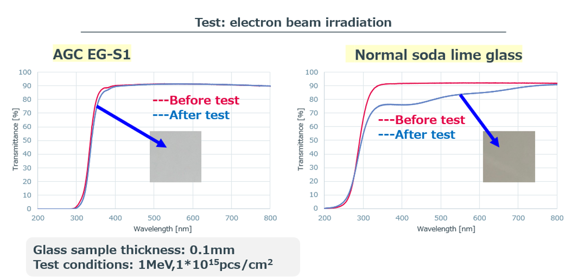
In addition, EG-S1 employs a specialized edge-processing technology that suppresses microcrack formation and achieves high edge strength. This helps reduce the risk of breakage during assembly and handling, making it easier to support designs with even thinner thicknesses.
EG-S1 is not merely a thin glass material. It is a glass product specifically designed for space applications, with edge quality, strength, and environmental resistance in mind. It can meet a wide range of design requirements, from ultra-thin configurations focused on weight reduction to thicker configurations focused on high durability.
07/Conclusion|Balancing Material Performance and Process Feasibility in Satellite Cover Glass
For cover glass used in satellite solar cells, it is important to select a material with high strength and high transmittance and to ensure consistent quality throughout the mass production process, including cutting, edge processing, coating, and handling.
In space applications, where thinner glass is increasingly required, edge quality and localized contact stress have a greater impact than surface strength alone. For functional coatings, such as AR films and conductive films, it is also essential to balance improved optical performance with the control of warpage and film stress.
Therefore, what matters is not the material's performance alone but whether the design can remain stable and feasible in mass production. In particular, thickness design is a critical design parameter that affects strength, processability, coating suitability, and handling performance. Optimizing these factors in collaboration with the material manufacturer helps reduce development risk and achieve stable mass production.